In this project, you'll be modifying the West Marine switch that was selected to activate the project robot's master power, making it battle-ready by replacing the big red plastic key with a socket head cap screw. This will allow you to use an Allen key to turn the master power on and off, which should make activation more convenient and reliable. You'll also be wiring the switch into the system by crimping battery terminals onto the battery leads and installing Powerpole connectors for quick battery changes.
| Caution: Eye protection is required for all cutting, drilling, and grinding operations in this project. Caution: Review all of the general power- tool safety protocols described in Chapter 5 of Kickin' Bot (Cutting Metal), as well as the sections that correspond to the specific tools used below. |
Part 3: Connecting the Battery Leads
Now that you've got the Powerpole connector on the battery leads, you need to connect the other ends to the robot's master power switch (for the positive lead) and ground connection (for the negative lead). You will be using crimpers (both the hand-held and hammer style) to make these connections.
click on an image to enlarge it
|
|
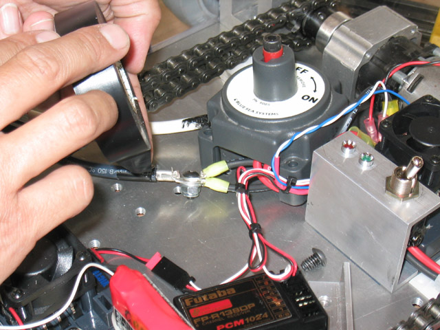
Route the power leads for the speed control further away from the master power switch around the battery and underneath the chain. They should nestle between the speed control near the master power switch and the secondary power switch bracket. The positive power leads for both speed controls should be trimmed near the location for the master power switch. Strip the red (positive) speed control power leads and crimp on a 12-10 GA 3/8"-stud ring terminal to each of the ends. [Note: In this picture, the previously-installed speed controls are missing.] |
|
|
Fasten the white battery lead onto the 3/8" terminal of the master power switch that faces the chain, and the speed control power leads should be routed so that the wires enter under the master power switch on the side that faces the battery. Try out the position of the switch and make sure that the leads aren't getting pinched. You may have to tweak the positions of the terminals a little bit. [Note: In this picture, liquid electrical tape has already been applied to the terminals. You will be applying it to your switch in a few steps.] |
|
|
You may have to grind away some of the master power switch brackets at the bottom with a Dremel tool to prevent pinching the wires. Don't worry- it's just plastic down there- the actual switching mechanism is at the top of the switch. |
|
|
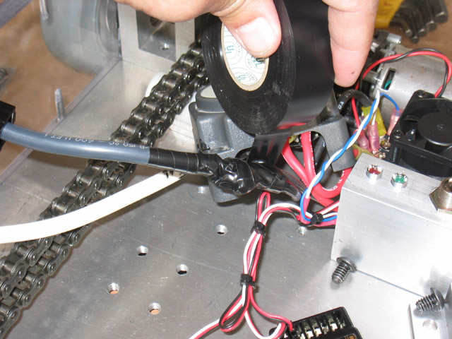
When you're satisfied with the positions, apply liquid electrical to all exposed metal underneath the master power switch. Lay out a rag underneath the switch to keep the base and other components clean. |
|
|
Trim the black (negative) power leads just past the secondary switch bracket, on the battery side of the master power switch. Strip the leads and crimp on a 12-10 GA 1/4"-stud ring terminal to each end. Fasten the black speed control power leads to the 8 gauge battery lead with a 1/4"-20 x 3/8" long button-head cap screw and a nylon-insert 1/4"-20 locknut, forming a star junction, as shown. |
|
|
Completely wrap the negative star junction with electrical tape, making tight spirals around the nut to prevent any short circuits to the baseplate. |
|
|
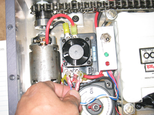
Strip the main power LED leads and crimp a 22-18 GA #8-stud ring terminal onto each lead. Because the wire is smaller than 22 GA, you should strip the end twice as long as you normally would, and then fold it back to double the diameter before crimping. Screw the main power LED leads onto the speed control that's closer to the master power switch, along with the fan leads, and the power input (12 GA) leads. You may have to shuffle things around and bend the LED's ring terminals a bit to get everything to fit. The fan leads, main power input leads, and main power LED leads should be installed on the "power in" terminals of the speed controls. Make sure to connect red (or white) to +V and black to GND. |
|
|
|