The secondary power switch will be used to turn the receiver on and off, saving the battery between matches. For maximum safety, you need power indicator lights for both the receiver battery and the main battery to tell you when either system is powered. In this project, you will prepare and install the secondary power switch and power indicator LEDs (light emitting diodes) on a mounting bracket and plug the PWM leads into the receiver. This will be an opportunity to get some more practice with the soldering iron as well as the stripper and crimper.
| Caution: Eye protection is required for these operations. Pieces of metal may fly around. Adequate ventilation is essential. Make sure not to inhale the solder fumes. Never blow on any solder joint to speed cooling. Allow the joint to cool on its own. |
Part 2: Preparing the Main Power LED
For the main power LED, you will repeat the above steps, but instead
of using a servo lead, use 24 or 26 gauge stranded hookup wire from the hardware store or an electronics vendor.
Use red or white for positive, and black or blue for negative. You will also use the red LED, a 1k-Ohm 1/2 Watt
resistor, and 1/8" red heat shrink (for the larger diameter 1/2 Watt resistor).
click on an image to enlarge it
|
|
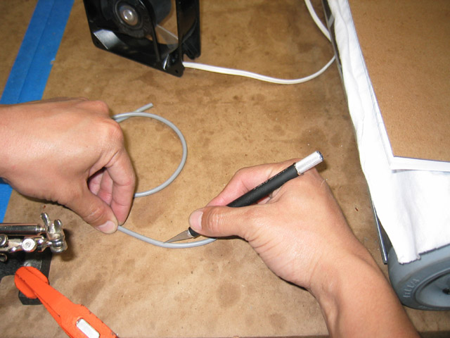
Cut off about 24 inches of wire. In this example, the two-conductor wire has an outer insulation jacket. Begin by scoring the outer insulation along its length about 2 inches from the end. |
|
|
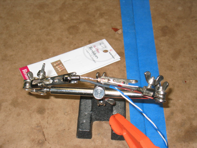
This will allow you to split the insulation and gain access to the wires inside. |
|
|
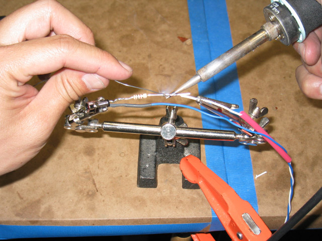
Strip 3/8" of insulation from the black lead. [Note: The blue lead in this picture should be black.] Cut a 3/4" long piece of 3/32" diameter black heat shrink tubing and slide it over the black lead. Wrap the black lead around the shorter (negative) leg of the red LED and apply the soldering iron and solder to the joint, as in the prvious step. Push the heat shrink tubing up over the joint and use a heat gun or lighter to shrink the tubing in place. |
|
|
Solder the 1k-Ohm, 1/2 Watt resistor on the positive lead, as shown. Do not substitute a 1/4 Watt resistor because it will be dissipating close to 1/4 Watt of power. As the amount of power dissipation approaches the resistor's power rating, the resistor tends to heat up dramatically, and may eventually fail, as well as lead to fire. By using a 1/2 Watt resistor, you avoid the the heat buildup. |
|
|
Cut a 2-1/2" long piece of 1/8" diameter red heat shrink and slide it over the white lead. |
|
|
Cut 1-1/2" off the white lead and strip 1/2" of insulation from the end. Wrap the white lead around the resistor and solder it in place. Cut off any excess wire that extends past the joint on either side with a pair of flush cutters. Slide the red heat shrink tubing over the resistor and use a heat gun or lighter to shrink it into place. Let the ends of the LED hang loose for now. They will need to be loose for installation in the switch bracket, which is coming up in a few steps. |
|
|
|