The secondary power switch will be used to turn the receiver on and off, saving the battery between matches. For maximum safety, you need power indicator lights for both the receiver battery and the main battery to tell you when either system is powered. In this project, you will prepare and install the secondary power switch and power indicator LEDs (light emitting diodes) on a mounting bracket and plug the PWM leads into the receiver. This will be an opportunity to get some more practice with the soldering iron as well as the stripper and crimper.
| Caution: Eye protection is required for these operations. Pieces of metal may fly around. Adequate ventilation is essential. Make sure not to inhale the solder fumes. Never blow on any solder joint to speed cooling. Allow the joint to cool on its own. |
Part 1: Preparing the Secondary Power LED
For this project, I chose a red LED for primary power and a green LED
for secondary power. Both had threaded housings to make mounting easier. The longer lead on an LED is the positive,
and the shorter lead is the negative. It doesn't matter which of these legs you put the resistor on, as long as
it's connected in series somewhere in the loop, although I usually put it on the positive leg out of habit. You
will begin by wiring the secondary power LED.
click on an image to enlarge it
|
|
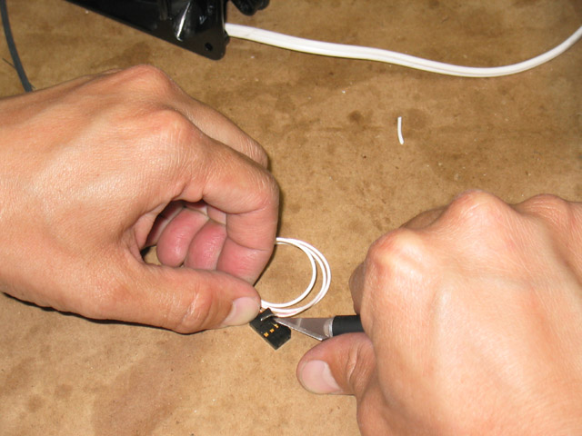
Use a 12" Futaba J-type servo extension for the secondary LED. It already has the right kind of connector to plug into the receiver. Cut off the female end close to the connector, leaving the male end as long as possible. (If you're unsure which is which, the male end is the one that can plug into the receiver.) Split the white lead off and use a hobby knife to lift the part of the plastic servo connector that holds the pin in place and slide the pin out, which will allow you to remove the white lead completely. |
|
|
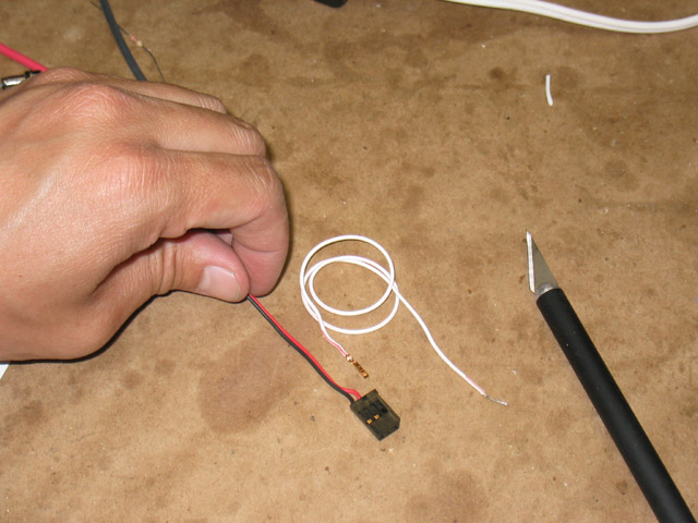
Separate the remaining red and black leads about 4-1/2" down, and strip 3/8" of insulation from the black lead. |
|
|
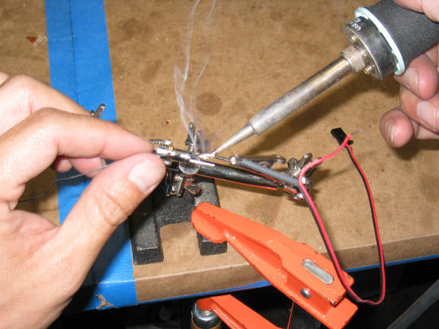
Cut a 3/4" long piece of 3/32" diameter black heat shrink tubing and slide it over the black lead. Wrap the black lead around the shorter (negative) leg of the green LED and apply the soldering iron and solder to the joint. Make sure that the solder left on the joint is bright and shiny. Do not blow on the solder to cool it. Let it cool down on its own. Cooling the joint too quickly will give you what's called a "cold solder joint," which can produce intermittent results. |
|
|
Push the heat shrink tubing up over the joint and use a heat gun or lighter to shrink the tubing in place. Make sure to keep the heat gun moving over the surface of the heat shrink so that heat it evenly. After a few moments, you will begin to see the heat shrink contract around the resistor. Let it cool on its own. |
|
|
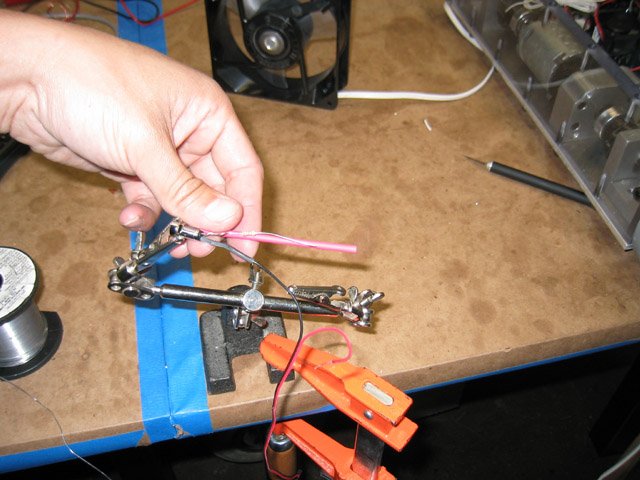
Solder the 220 Ohm, 1/4 Watt resistor on the positive lead, as shown. |
|
|
Cut a 2-1/2" long piece of 3/32" diameter red heat shrink and slide it over the red lead. |
|
|
Cut 1-1/2" off the red lead and strip 1/2" of insulation from the end. Wrap the red lead around the resistor and solder it in place. |
|
|
Cut off any excess wire that extends past the joint on either side with a pair of flush cutters. Slide the red heat shrink tubing over the resistor and use a heat gun or lighter to shrink it into place, as described above. |
|
|
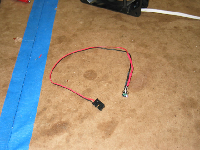
This is the completed secondary LED wiring harness. |
|
|
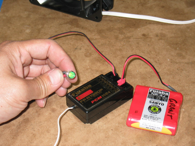
You can test the secondary power LED by plugging it into the receiver and plugging in the receiver battery. |
|
|
|