In this project, you will install brackets to hold the receiver and its battery. You will also mount the speed controls and the main battery. You'll get some experience with extruded aluminum material, which is available in many useful profiles, such as U and L. Velcro (along with a secondary restraint) will be used as shock-absorbing and mounting material for these sensitive electronic components.
| Caution: Eye and ear protection are mandatory for cuts using the miter saw. It is incredibly loud, and pieces of metal will be flying everywhere. When using the rest of the tools in this project, you will need eye protection. Review all of the general power-tool safety protocols described in Chapter 5 of Kickin' Bot, as well as the sections that correspond to the specific tools used below. |
The battery rails will help prevent the heavy main battery from sliding around on the inside of the robot. They will be simple lengths of L-channel bolted to the base plate. The receiver battery bracket and the switch bracket (see Project 7) will also be mounted around the battery so that it's captured on all four sides.
click on an image to enlarge it
|
|
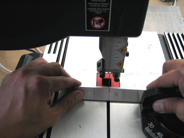
Using the miter saw or the bandsaw, cut two 2 inch long pieces of 3/4" extruded aluminum L-channel. |
|
|
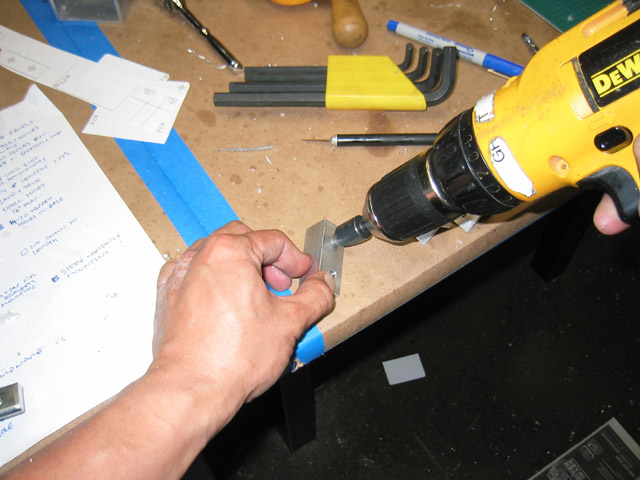
Note that when using the miter saw, you'll need a scrap block of metal to apply the clamping pressure to the L-channel, which sits too far back for the clamp to normally effectively hold it in place. The application of the scrap block is shown on the left side of this picture. As before, make sure that the workpiece sits flat on the table in the area around the blade. |
|
|
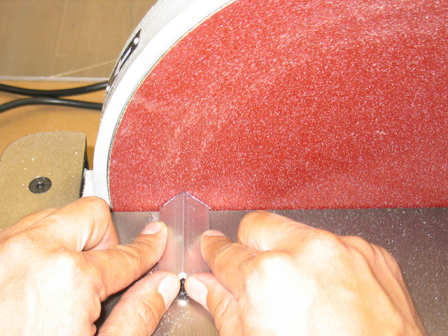
Clean up the cuts on the disc sander. Make sure that the part is held perpendicular to the abrasive surface as shown. |
|
|
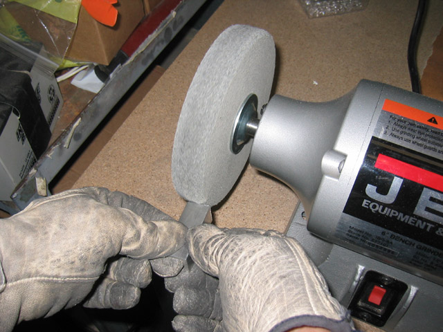
Remove the sharp edges with the deburring wheel. You may need gloves if the part gets too hot. You can cool the aluminum in a bowl of water when you're done. |
|
|
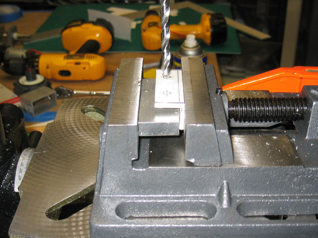
Apply the hole pattern with spray adhesive and mark the holes with an automatic center punch. When clamping the L-channel in the drill press vise, use a scrap block of aluminum to get a better hold, similar to the way you clamped the U-channel before. Drill two 1/4" holes in each piece. |
|
|
Make sure to deburr all holes with a countersink. |
|
|
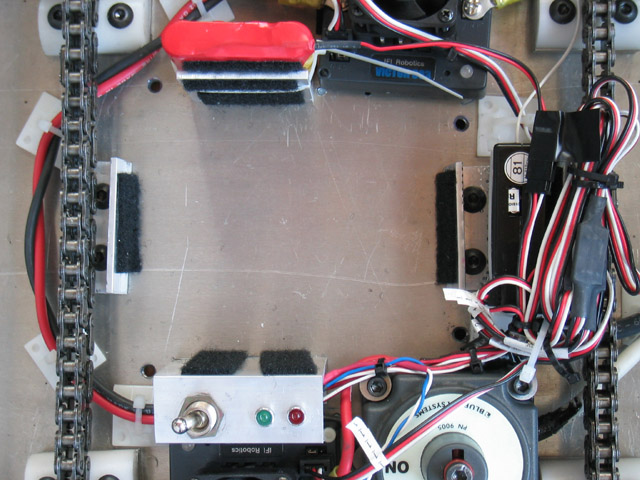
Install the rails on the base using 1/4"-20 x 3/8" long button-head cap screws with Loctite. In this picture, the battery rails are at the left and right sides. Apply velcro to the battery rails. Later, you will also apply velcro to the receiver battery bracket and the switch bracket, which are at the top and bottom of the picture. Here, the velcro is being used to provide a cushion (so the battery doesn't rub on bare metal), and to provide a little extra grip. |
|
|
|