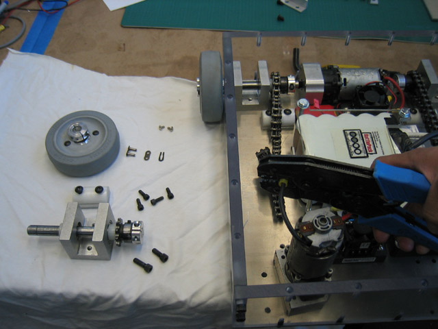
In this project, you will install brackets to hold the receiver and its battery. You will also mount the speed controls and the main battery. You'll get some experience with extruded aluminum material, which is available in many useful profiles, such as U and L. Velcro (along with a secondary restraint) will be used as shock-absorbing and mounting material for these sensitive electronic components.
| Caution: Eye and ear protection are mandatory for cuts using the miter saw. It is incredibly loud, and pieces of metal will be flying everywhere. When using the rest of the tools in this project, you will need eye protection. Review all of the general power-tool safety protocols described in Chapter 5 of Kickin' Bot, as well as the sections that correspond to the specific tools used below. |
In this series of steps, you'll connect electrical leads to the speed controls using the stripper and crimper and mount them to the baseplate using Velcro. (Other shock mounting options are discussed in Chapter 8.) Since the Velcro won't be enough to hold the speed control in place, we'll use screws as a secondary restraint.
click on an image to enlarge it
|
|
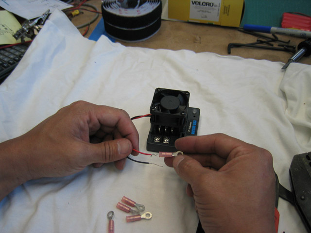
First, cut down the fan leads to 4" and crimp on a 22-18 GA #8-stud ring terminal to each lead. Because the wire is smaller than 22 GA, you should strip the end twice as long as you normally would, and then fold it back to double the diameter before crimping. |
|
|
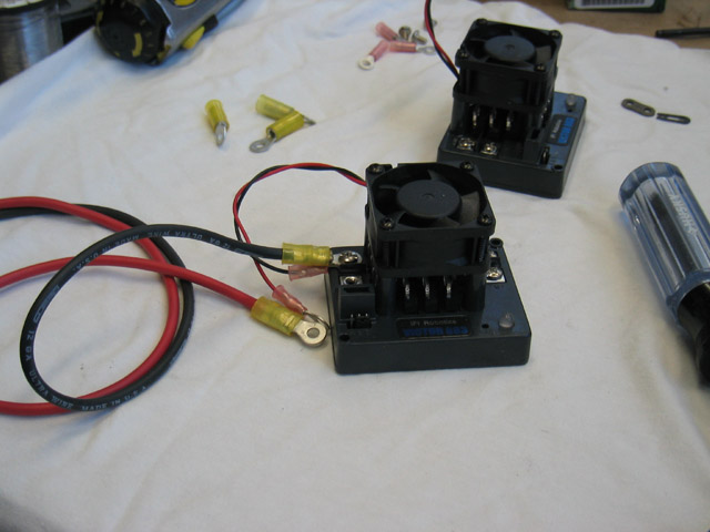
Cut a 4" and 16" length of both red and black 12 GA Deans Ultra or Wet Noodle wire. As you can see, the 16" length will wrap all the way around the battery. I didn't pass wires directly over the battery because I wanted to keep that area clear, which makes changing batteries easier. |
|
|
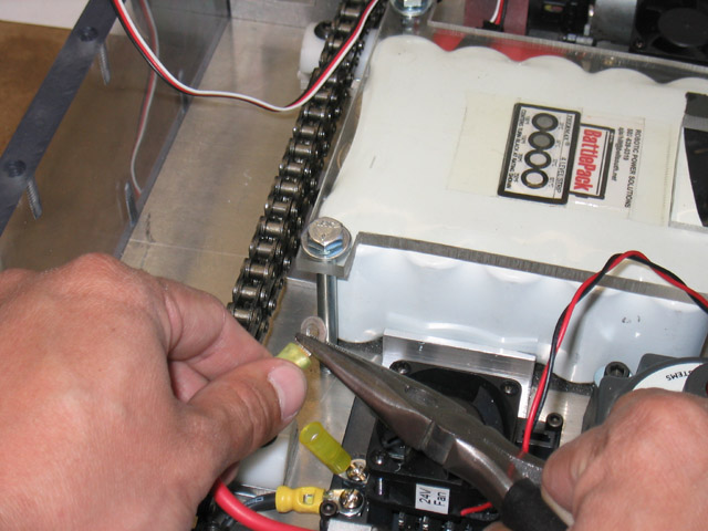
Strip the ends and crimp on a 12-10 GA #8-stud ring terminal to one end of each lead. Remember to check every crimp, every time. As the saying goes, "You live and die by your crimps." |
|
|
Screw the 4" pair onto the speed control that will be mounted closer to the master power switch, along with the fan leads. Twist the red and black leads together on the 16" pair and connect it to the other speed control along with its corresponding fan leads. Both the 12 GA wires and the fan leads should be installed on the "power in" terminals of the speed controls. Make sure to connect red to +V and black to GND. |
|
|
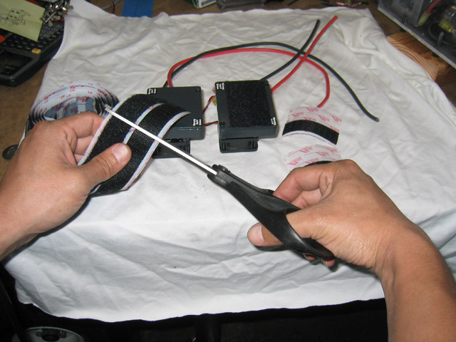
Apply Velcro to the bottom of both speed controls and to the base plate. |
|
|
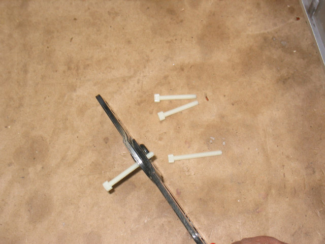
Cut down the 6-32 x 1-1/4" long alloy steel socket-head cap screws with a crimper that has a built-in bolt cutter, as described in Chapter 8. [Note: The nylon screws shown in this picture were later changed to alloy steel after they sheared off during testing.] |
|
|
Attach the speed controls to the Velcro on the base plate and secure them with the alloy socket-head cap screws. Route the longer pair of leads around where the battery would be. Once the speed controls are mounted, you can pull the motor leads over to them and trim them off, leaving a little slack. Strip the ends and crimp on a 12-10 GA #8-stud ring terminal to each lead. |
|
|
You may have to pre-bend the ring terminals to give your wires a little extra clearance. Use a pair of needlenose pliers to make the bend. |
|
|
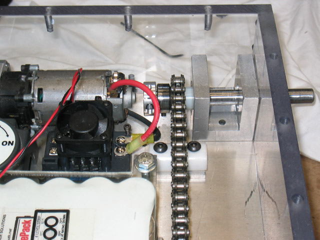
Screw the terminals on to the motor outputs of the speed controls, making sure to flip the polarity of one set of leads. (Remember that one of the motors has to turn backwards for the robot to move forward.) Make sure that the wires are at least 1/2" from the chain when installed. [Note: In my initial parts layout, I put the speed controls too close to the chain. If you want to see how I fixed this, check out the Moving a Component That's Already Mounted tip.] |
|
|
|