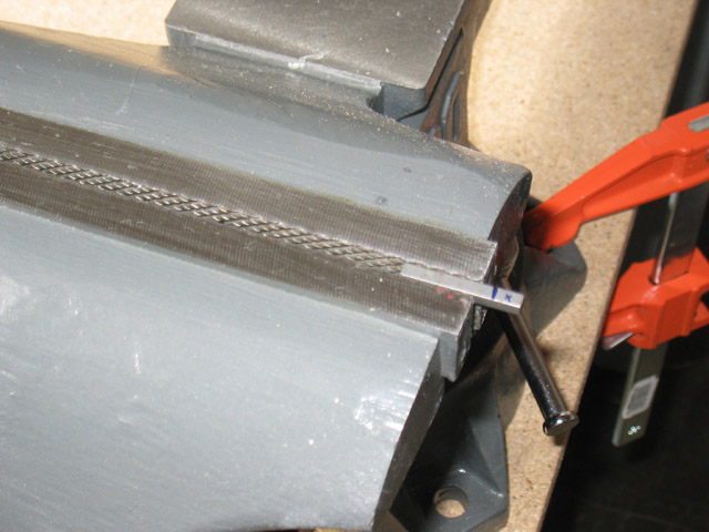
So far, you've cut out all the armor plates and drilled all the holes for your project robot. You're almost ready to bolt everything together. In this project, you will prepare the polycarbonate plates, axles, motors, and other drive system components for assembly and fasten them to the base. You'll get practice in preparing Lexan (no sharp edges, as mentioned in Chapter 4), as well as your first taste of soldering with the motor leads, and cutting steel for the axles.
| Caution: Eye protection is required for all of these operations. Review all of the general power-tool safety protocols described in Chapter 5 of Kickin' Bot, as well as the sections that correspond to the specific tools used below. |
Part 5: Assembling the Drive Components
In order to prevent the shaft from simply pushing out of the bearing,
you've got to lock it in place. Thanks to the excellent engineering by Dan Danknick of Team Delta, the bearings
in these blocks are captured on opposite sides. This means that you can prevent the shaft from sliding by putting
a shaft collar on either side of the block. Note, however, that you want to only touch the center of the bearing,
which spins along with the shaft. Otherwise, you'll cause drag. To deal with this, we'll use some smaller diameter
nylon spacers to make sure that we only touch the center of the bearing. We'll also use them to correctly space
the sprocket on the shaft.
click on an image to enlarge it
|
|
Use the 1/2" bore x 5/8" OD x 3/8" long nylon bearings as spacers on the inside and the 1/2" bore x 3/4" OD x 1/2" long nylon bearings as spacers on the outside towards the wheel. If the nylon spacer is too tight, you may have to open up the hole just a bit with a Uni-bit. Don't clamp the spacer too tightly in the bench vise, or you'll compress it and cause and oblong hole. Just clamp it tightly enough to grip the part. |
|
|
In order to install the sprockets, you need to clamp the keys in the bench vise and cut them down to 3/4" long with a hacksaw. (They're a bit too long right now, and will stick out of the sprocket if installed.) Use the disc sander and deburring wheel to clean up the edge of the key. |
|
|
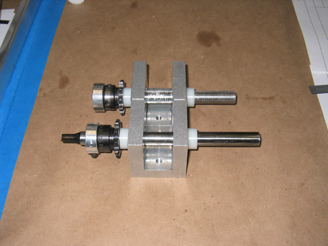
Assemble the axle, spacers, shaft collars, and sprockets (with keys) on each bearing block as shown. (Do not install the wheel and wheel key yet. Those items will only get in the way, and will be installed just before the drive test.) The teeth of the sprocket face towards where the wheel would be, and the shaft collar goes on the axle right behind it. |
|
|
The splined axle will be assembled exactly the same way, with the spline sticking out of the sprocket side. As mentioned in the previous step, do not install the wheel and wheel key yet. Those items will only get in the way, and will be installed just before the drive test. |
|
|
This picture shows the final assembly of one side of the drive. Feed the axles through the axle holes in the side panels. Fit the motors onto the splined shafts. The motors should be mounted with 10-24 x 1/2" long button-head cap screws. You may have to tweak the position of the splined shaft if it jams up against the motor. Under normal conditions, the motor should have a little play, allowing you to rock the splined shaft back and forth. If it feels too tight, then adjust the shaft collars so that the tip of the splined shaft moves more towards the outside of the robot, away from the motor. Apply Loctite to all screws once you're satisfied with the position of everything. Avoid getting any Loctite on the polycarbonate. |
|
|
|