The first project is actually more of an introduction to the robot that you will be building in the rest of the projects that follow. It explains the design choices I made with regard to materials, electronics, and mechanical parts. Don't worry- you'll be getting to the nuts-and-bolts building in Project 2: Cutting the Armor Pieces.
The project robot is small. It's basically a 15" x 14" x 3.5"
box with four wheels. I started by scaling the armor, drive, and electronics components for a 60-pound (lightweight
class) robot. However, since this robot has no weapon, there were about 30 pounds left over, which is 50% of the
total weight. The difference between this ratio and my recommended ratio of 30% for the weapon system will be offset
by the larger frame that would be required to fit all of the weapon components.
click on an image to enlarge it
|
|
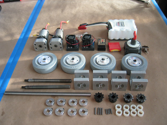
Here is the pile of unassembled parts that you will begin the project with. These parts are described in more detail in the following steps. |
|
|
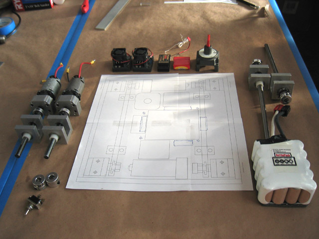
To save time, I've based the projects around paper templates that tell you where to drill the holes and how to cut certain pieces. You will print out the templates and paste them to the metal or plastic to mark your holes, as described in the projects. The overall layout should be downloaded from this site and printed out 1:1 scale. Alignment marks are provided for taping together smaller sheets to get the complete layout. This picture shows a full layout sheet (taped together) in the middle. |
|
|
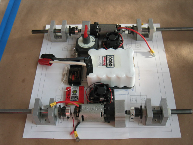
One of the design goals of this robot was to get as many of the sensitive components (speed controls, receiver, and so on) as far away from the edge of the robot as possible, as shown in this parts layout. That way, any penetrating weapons would have to travel quite a ways to get at them. Although it might have been more direct to mount components in the space above the battery, or pass wires across the top, I decided to keep the space open, so that the battery can be changed easily. |
|
|
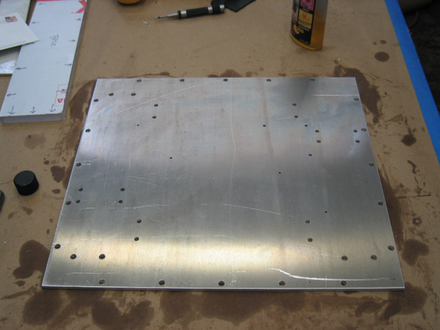
The 3/16" thick aluminum baseplate is thicker than really necessary for this robot, since many robots in the 60-pound weight class get away with 1/8" thick bases. However, I want to give you practice cutting thicker plates. |
|
|
The sides are made of 1/2" thick Lexan, which gives you enough thickness to create a screw thread into the side of the piece for mounting to the base. Since most attacks come from the sides, I opted for a thinner piece of 1/4" thick Lexan for the top armor to keep the weight down. Choices for robot-building materials are discussed in Chapter 4, "Selecting Materials." |
|
|
The drive system is pretty basic. On each side of the robot, one wheel will be directly driven by a DeWalt drill motor, while the other wheel will be driven by a roller chain and sprocket system connected to the same motor. The project robot uses a Team Delta RCM500 DeWalt motor mount for each drill motor, and RCM200 bearing blocks for each wheel. |
|
|
The wheels are Colson caster wheels. They are battle-proven to have excellent traction in a number of different arenas. These wheels were purchased pre-assembled from Team Delta ready for mounting, with keyways already cut into the hubs. Chapter 12 ("Let's Get Rolling") lists various wheel and hub choices, as well as drive layout considerations. The caster wheel is pictured here with a Team Delta RCM200 bearing block. |
|
|
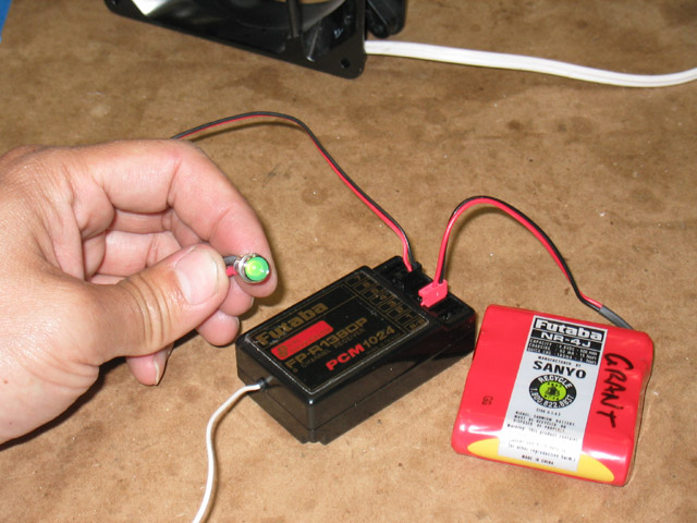
The control system for this robot will be a Futaba 9CAP radio control package. The accompanying receiver will have its own battery, with a separate on/off switch. Control systems are covered in Chapter 13, "Choosing Your Control System," while programming issues are explored in great detail in Appendix A, "Advanced Radio Control Programming." |
|
|
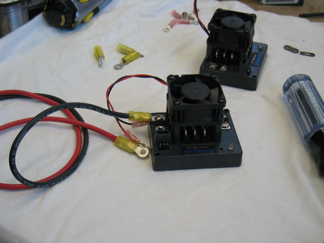
The IFIrobotics Victor 883 speed controls were selected for this project because they are affordable and easy to obtain. They are also single-channel speed controls, so you will get some practice in manually enabling the elevon mixing on the radio as described in Appendix A, "Advanced Radio Control Programming." All of the major speed controls are discussed in Chapter 14, "Choosing Speed Controls." |
|
|
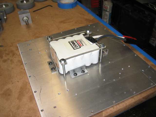
The main battery will be a single 3.6 AHr NiCad BattlePack, made by Robotic Power Solutions. You've also got to purchase a spare battery, a charger, and a power supply for the charger. Battery selection and technologies are discussed in Chapter 15, "Choosing Batteries." |
|
|
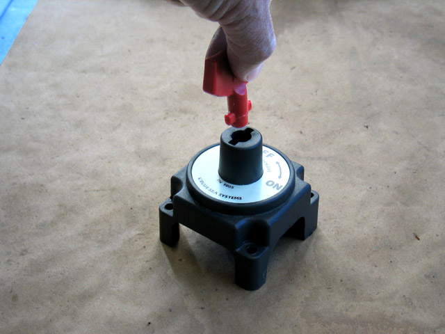
A West Marine power switch was chosen because of its ease of mounting and shock resistance. Some modifications will be necessary to the switch to make it ready for competition. Power switches, wire and connectors, and techniques for using them are discussed in Chapter 16, "Wiring the Electrical System." |
|
|
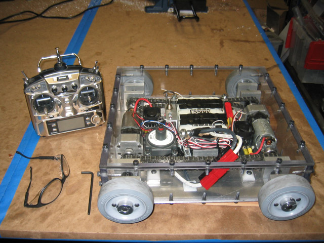
Here is the completed project robot, along with the Futaba 9CAP transmitter. Ready to get started? Then click the "next" button below! |
|
|